Jump to video!
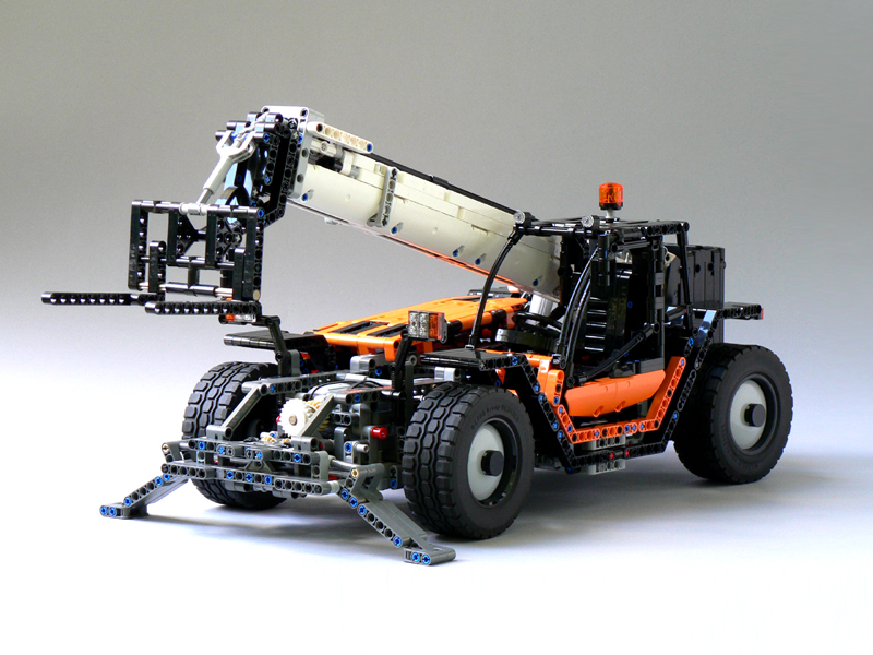
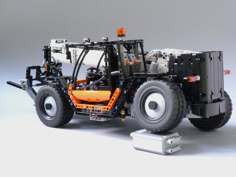
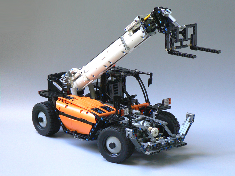
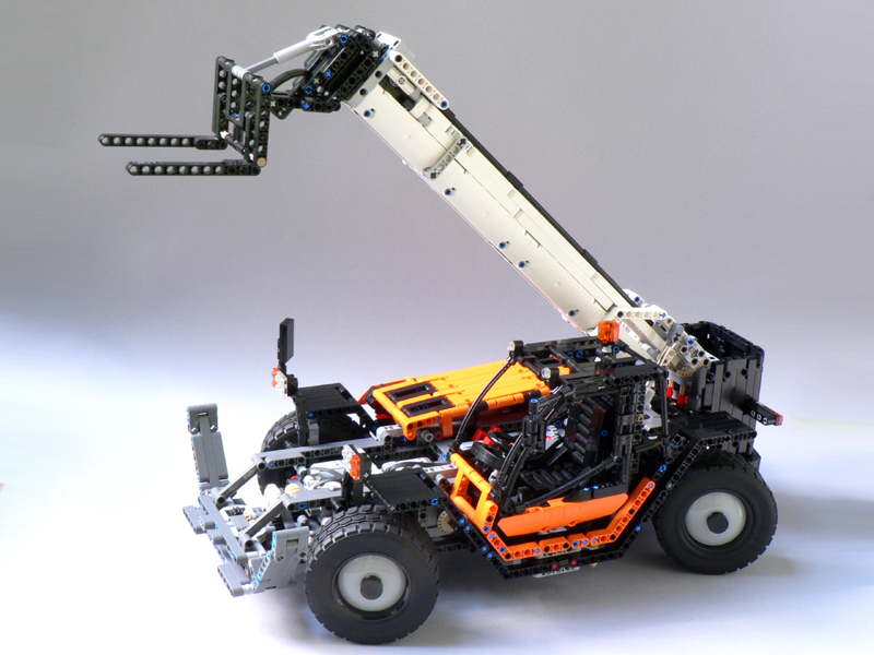
Features:
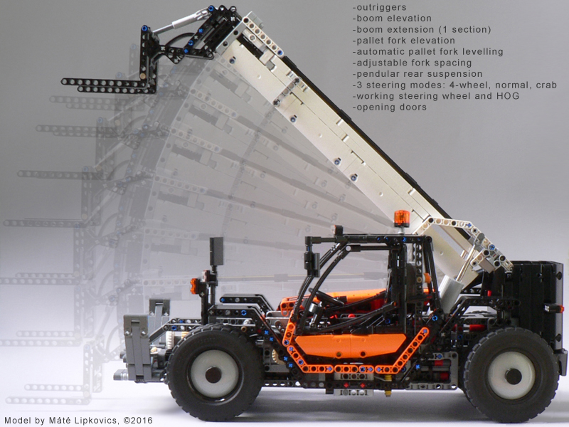
- Outriggers
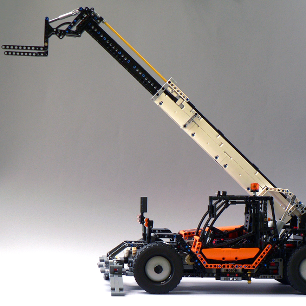
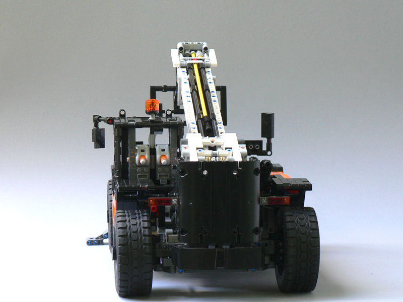
- Boom elevation
- Boom extension (1 section)
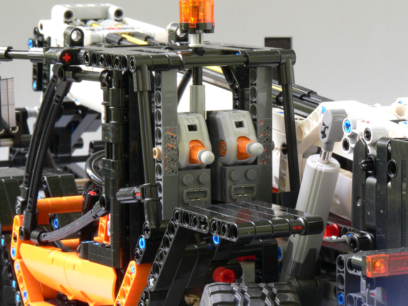
- Pallet fork elevation
- Automatic pallet fork leveling (the fork stays in level during boom elevation/extension
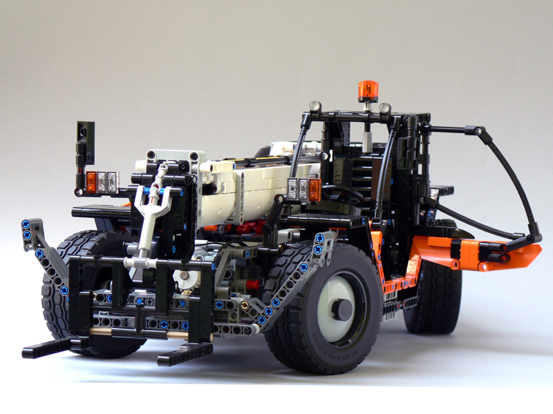
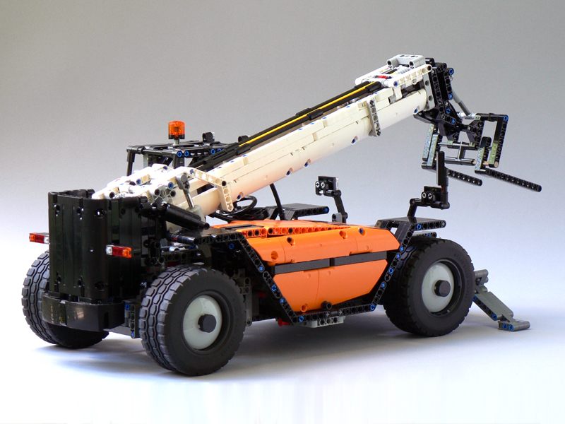
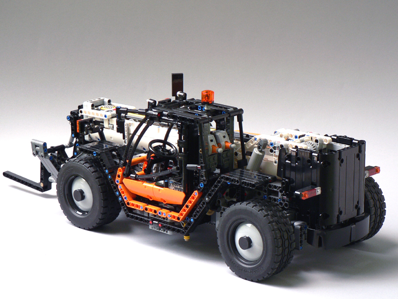
- Pendular rear suspension
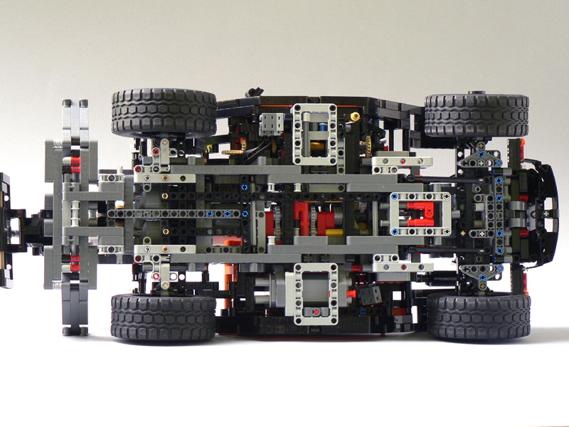
- 3 steering modes: 4-wheel, normal and crab (Barman's linkage)
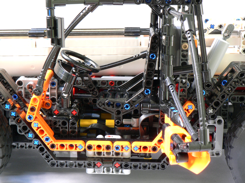
- Working steering wheel and HOG
- Opening doors
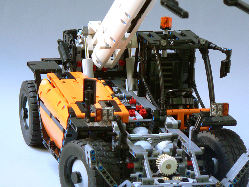
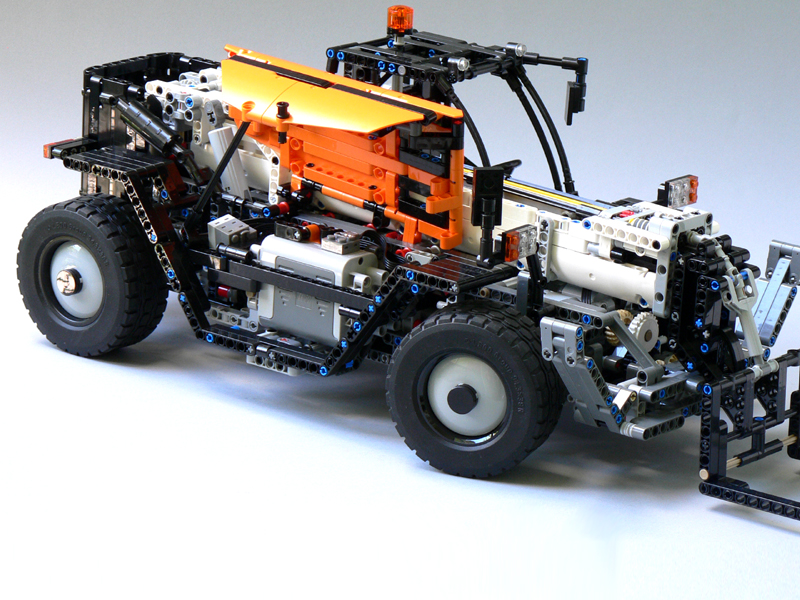
The model contained three L-motors, two of which were powering the elevation.
There was a gearbox for two operation modes: boom elevation+extension and outriggers+fork elevation.
The functions could be operated with two PF pole reversers.
Design process and challenges
The building time of the model was almost three years with long pauses and some complete start-overs. The building started in January, 2013 and that time it was and still it is the most complicated model I've made.First prototype (January, 2013-)
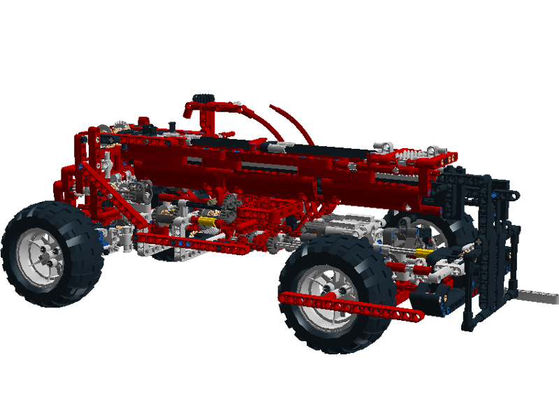
The point of the build was the automatic pallet fork leveling because no telehandler model with extending boom had this feature up to that date, even though it's an important playability feature (not only realistic). Without this, the operator always has to readjust the pallet fork during boom elevation.
The task was hard by itself but I set up an additional requirement: not using the 32L axle part to make it possible to build the boom with theoretically any length. This requirement resulted in an overcomplicated dual boom system, where two beams running parallel would make up the inner boom, and the displacement between the two beams caused the fork to tilt. The drive of the booms and the displacement was achieved by an adder (differential).
The automatic leveling would have been achieved with another adder that added the main booms rotation to the drive of the tilting boom.
This complex gearbox and the boom was simply too complicated and flimsy for this (and pretty much any) scale. The gearbox to the boom elevating actuators was also too complex because of the placement of the actuators - which were too weak and very off-scale anyway in that setup (ride side of the picture below).

Only the boom and the chassis part below it were built with real bricks but it was enough to give up on the project and go for simpler learning projects. Below is a screenshot of one sub-prototype.
Second prototype (October, 2014-)
The second building course started with realizing that my model will not be big enough to utilize the unlimited-long boom concept, so the simpler 32L sliding axle construction was used.
The other important concept change was the automatic fork leveling concept. Instead of the complicated differential system, I tried to implement the feature simply by coupling the two drive-trains with a proper gear ratio. Also, I changed the actuator setup for vertical placement which meant a much simpler gearbox.
The reason why this prototype was not finished was the steering, only two steering modes were implemented and the system sometimes jammed due to the knob-gears' slight jamming in parallel setup. Also there was no convenient placement for the motors.
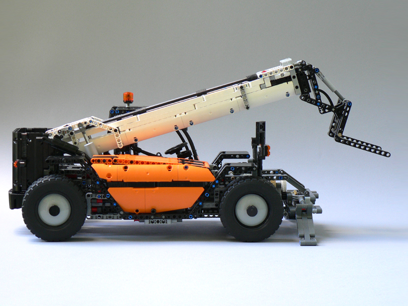
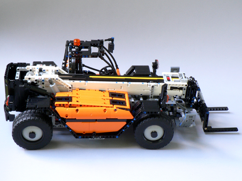
The boom, the proportions and the overall body design made it to the final version.

Final model (April, 2016)
The 42054 Claas Xerion model with leaving out the drive-train and with its continuous steering mode switching (and more importantly a possible implementation presented by Barry Bosman, a.k.a. Barman) was inspiring enough to continue work. I made a prototype chassis with the steering and found a place for the two motors above the front axle which became more flat by the lack of drive and differential. With the steering system being only 3 studs high, a third motor could be placed inside the chassis so the boom elevation driven by two motors became quite powerful.
The long development really payed off but I believe I could design a model like this with a much smaller effort now - most of the struggle was caused by the lack of experience when I started the project.
The model was included in Thirdwigg's Top 16 of 2016 list.

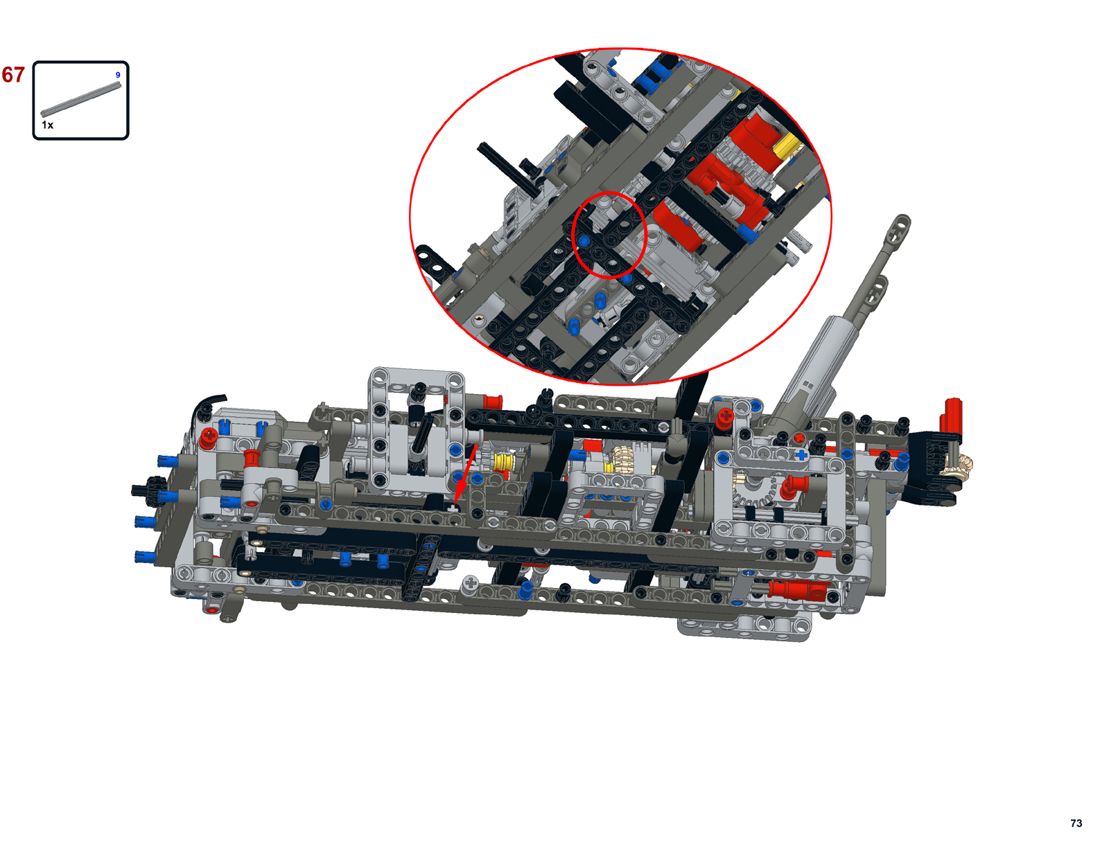
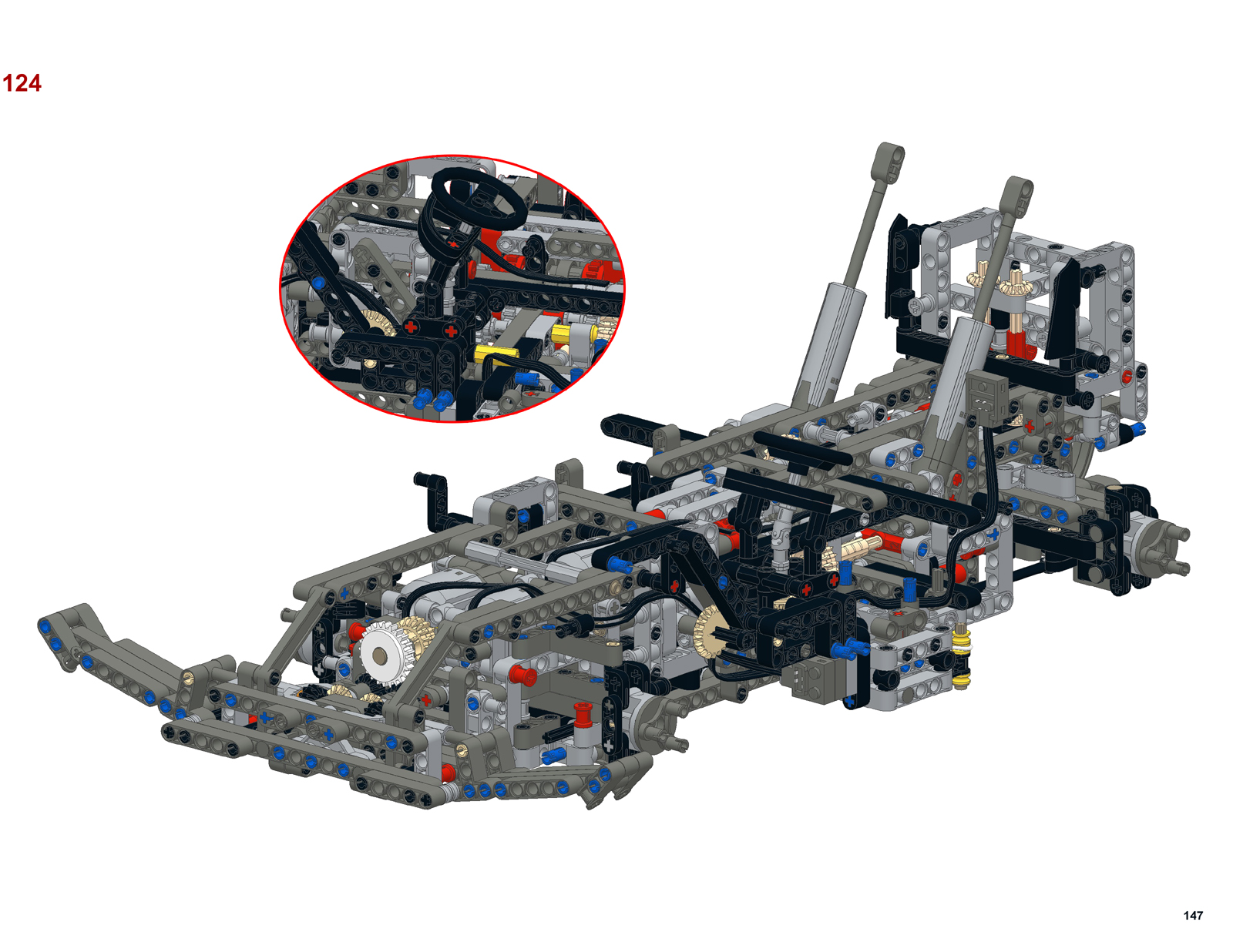
Instructions were made for this model like my previous one but this time I took a different approach and avoided using floating assemblies as it can cause many parts list per page errors in the LDraw environment. So instead of floating assemblies, alternate views were used to show how parts or subassemblies are attached to each other. You can find the model on Rebrickable.com or download the pdf instructions directly.

External links: